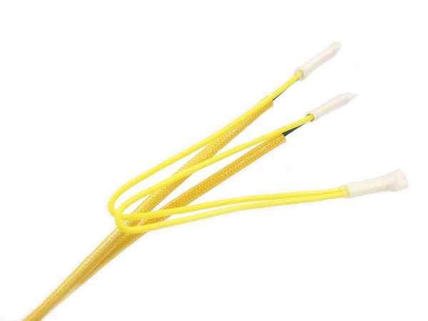
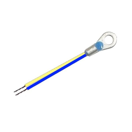
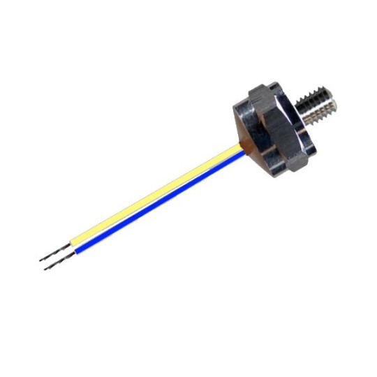
 TP or PTC is a small non-linear resistance sensor, which can be integrated into the winding of electric motors. This meter is made from metal oxide or semiconductor material.
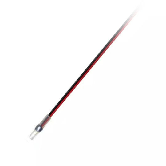
The advantages of the nonlinear PTC - PTC thermistor probe
 Their small size of the PTC temperature sensor allows it to be installed in direct contact with the stator winding.
- Their low thermal inertia gives a fast and precise response to winding temperature changes.
- Thermistors can measure temperature directly regardless of how those temperatures are initiated.
- Nonlinear PTC thermistor probes can be used to detect overload conditions in motors driven by variable frequency drives.
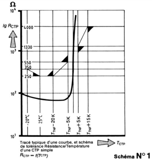
The resistance change is relatively small and remains almost constant up to the nominal response temperature. When the nominal response temperature is approached and exceeded, the resistance gradient increases sharply, giving the PTC thermistor high sensitivity to the slightest variation in temperature.
At the Curie point, a temperature increase of a few degrees causes a large increase in resistance. The resistance is monitored by a protection relay and when a large change in resistance is detected by the protection relay, it actuates a contact to trigger an alarm or shut down the protected device.
Thermistor protection relays should reliably trip when the resistance of the temperature sensor exceeds approximately 3 kΩ.
These PTC meters also react to an open circuit, either in the cable or in the thermistor sensor, thus providing protection against failure. Modern relays are also designed to detect a PTC sensor short circuit, when the resistance of the sensor drops below about 50 Ω.
These temperature sensors are frequently used in AC variable speed drives to protect the AC motor powered by inverters. Many modern AC drives have a built-in thermistor protection unit thus avoiding the use of a separate thermistor protection relay.
Tripping temperature according to the insulation class of the electric motor
| Motor insulation class | E | F | H |
| Lower rated temperature | 120°C | 140°C | 165°C |
| Alarm temperature | 120°C | 140°C | 165°C |
| Trigger temperature | 120°C | 140°C | 175°C |
General technical characteristics
| Max. operating voltage | Vmax | 30V |
| Max. measurement voltage | Vmeas, max | 2,5 V |
| Nominal resistance (2,5 V max) | R25 | ≤100ohm |
| Insulation voltage | V | 2,5 kV |
| Ts response time | t | ≤5 seconds |
| Detection temperature tolerance Ts | ΔT | ±5K |
| Max. Operating temperature range (V≤Vmeas, max) | ° C | 200C |
The use of nonlinear thermistor measuring instruments
Precaution for use
Due to the relatively slow transfer of heat to the sensors through the insulation, PTC thermistor probes do not provide fast enough protection against short circuits in motors or transformers.
Also, since they are usually located in the stator windings, they do not provide adequate protection for critical motors or high inertia starting or locked rotor conditions.
In these cases, to achieve complete protection, it is recommended to use PTC thermistors in combination with electronic motor protection relays, which monitor the primary current drawn by the motor. The application of PTC thermistors as temperature sensors is only effective when:
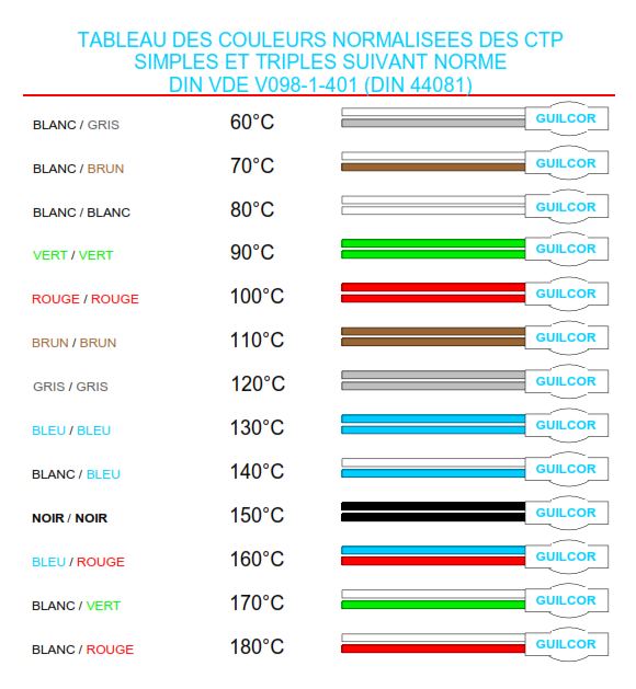
1. The rated response temperature of the thermistor is correctly selected for the insulation class used on the winding.
2. Thermistors are correctly located near thermally critical areas.
3. There is a low thermal resistance between the winding and the PTC thermistor.
Multiple thermistor sensors can be connected in series in a single input relay, provided the total resistance at ambient temperatures does not exceed 1,5 kΩ. In practice, up to six thermistor sensors can be connected in series.
Since thermistors must be insulated from high voltages, it is more difficult to achieve low heat transfer resistance in HV motors, which have greater insulation thickness.
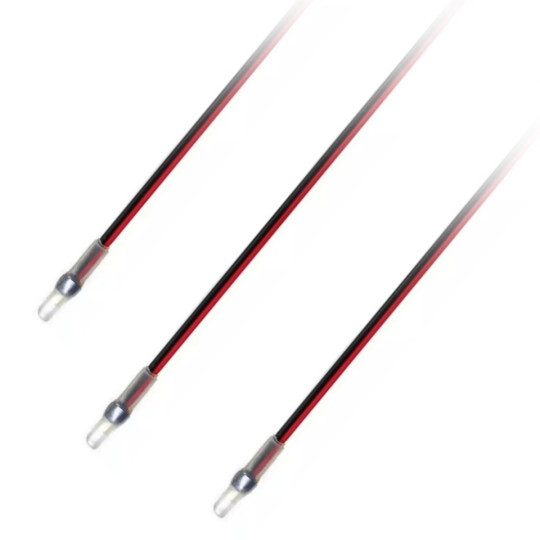
The use of the PTC measurement probe and three-phase motors
For a three-phase AC motor, two thermistor sensors are usually provided in each of the three windings and connected in two groups of three series. One group can be used for alarm and the other group for motor triggering. The alarm group is usually selected with a lower rated response temperature, typically 5 ° C or 10 ° C lower than the trip group.
If the operator takes no action, the trip group is used to stop the motor to prevent damage to the winding insulation. The physical location of thermistor sensors in an AC motor depends on the construction of the motor, whether it is a cylindrical rotor or a salient pole rotor, and several other design and construction variables. manufacturing.
In some cases, the optimal location may need to be determined from real-world testing.
Relays for non-linear PTC thermistors
 The thermistor protection relay is designed to be mounted inside a control cabinet or motor control center, usually on a standard Din rail.
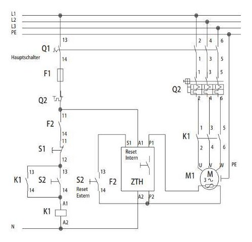
The figure below shows a typical connection of two thermistor protection relays, and their associated groups of temperature sensors.
For alarm and trip control of a three-phase AC induction motor. The performance of thermistor protection relays can be affected by external electrical interference, where voltages can be induced in the sensor cable.
Therefore, the cables between the thermistor protection relay and the non-linear PTC thermistor sensors should be selected and installed to minimize the effects of induced noise.
Cables should be kept as short as possible and should avoid running near noisy or high voltage cables for long distances!
During the tests, care must be taken not to blow the thermistor probes, as this may damage them!!
The correct procedure is to connect all the thermistor leads together and apply the test voltage between them and ground or phases.
Some practical recommendations for the type of cables to be used are as follows:
- Distances ≤ 20 m - Standard parallel cable is acceptable
- Distances ≥ 20 m, ≤ 100 m - Twisted pair cable is required
- Distances ≥ 100 m - A shielded twisted pair (STP) cable is required
- High interference level - Shielded twisted pair (STP) cable is required