Delivery in 3 to 5 weeks


Reference GNS110R

ACCESSORIES
DECLARATION, CERTIFICATION, CALIBRATION
Attention: 4-20 mA output temperature sensors can be delivered with the new connection head only in version A.
| Sensor type (K - with connector) |
NS 110x NS 110XK |
NS 111x NS 111XK |
NS 112x NS 112XK |
NS 310x NS 310XK |
NS 311x NS 311XK |
| Sensitive element type |
Nor 1000/5000 | Nor 1000/6180 | Ni 891 | Nor 10000/5000 | Nor 10000/6180 |
| Measuring range |
-50 to 100 ° C | ||||
| Current continuous from maximum measurement |
1 mA | 1 mA | 1 mA | 0.3 mA | 0.3 mA |
| Sensor type (K - with connector) |
NS 113x NS 113XK |
Pts 110x PTS 110xK |
Pts 210x PTS 210xK |
Pts 310x PTS 310xK |
HS 110X HS 110xk |
| Sensitive element type | T1 = Ni 226 | PT 100/3850 | PT 500/3850 | PT 1000/3850 | 20 kΩ NTC thermistor |
| Measuring range | -50 to 100 ° C | ||||
| Current continuous from maximum measurement |
0.7 mA | 3 mA | 1.5 mA | 1 mA | 0,3 mW *) |
*) maximum power consumption
| Sensor type (K - with connector) |
NS-510A NS-510AK |
NS 710x NS 710XK |
Footnotes |
| Sensitive element type | Point 1000/3850 | PT1000/3850 | |
| Output signal |
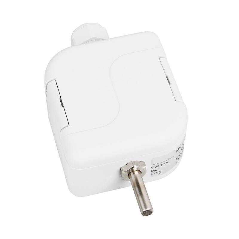
4 to 20 mA | 0 to 10 V | |
| Measure the edges |
-30 to 60 ° C 0 to 35 ° C 0 to 100 ° C 0 to 150 ° C |
-30 to 60 ° C 0 to 35 ° C 0 to 100 ° C 0 to 150 ° C |
Ambient temperature around the connection -30 to 70 ° C |
| Power supply (U) | 11 to 30 V DC | 15 to 30 V DC | Recommended value 24 V DC |
| Resistance to load Rz | 150 Ω for 12 VDC power supply 700 Ω for 24 VDC power supply |
> 10kΩ | |
| Output signal - braek sensitive elements |
> 24 mA | > 10.5 mA | |
| Output signal - short sensitive element |
<3.5 mA | ~0V |
Note: x = version A or version B
**) Depending on customer requirements, it is possible to provide a custom measurement range from -40 to 150 ° C; the minimum range of the range must be 35 ° C (for example, -20 to 15 ° C; -30 to 80 ° C)
| OTHER PARAMETERS | |
| Precision class |
Sensitive elements Ni: class B, t = ± (0,4 + 0,007 t), for t ≥ 0; t = ± (0,4 + 0,028 | t |), for t ≤ 0 in ° C; Elements sensitive to pt: class B according to EN 60751, t = ± (0.3 + 0.005 | t |) in ° C NTC 20 kΩ: ± 1 ° C for the range from 0 to 70 ° C |
| Measurement error NS 510A (K), NS 710x (K) |
NS 510A ± 1 ° C (depending on the air flow speed) NS 710A 0,6% for the range with span; min. 0,5 ° C |
| Connection of sensors |
according to the wiring diagram |
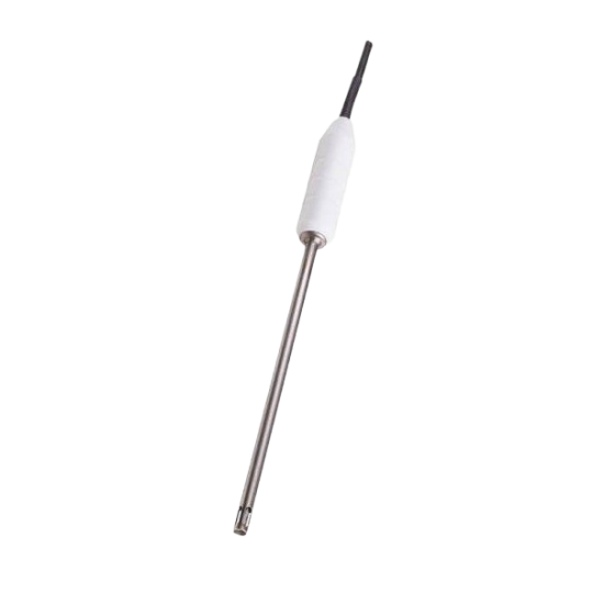
| Standard rod length (version A) | for resistance output and for 0 to 10 V output: 25 mm for 4 to 20 mA output: 50 mm |
| Response time |
τ 0,5 <9 s (air flow at 1m s -1 ) - version A τ 0,5 ≤ 30 s (air flow at 1m s -1 ) - version B |
| Recommended wire section - sensors with grommet |
0,35 to 1,5 mm 2 |
| Connector type in the head - sensor with connector |
RSFM4 - Lumberg |
| Isolation resistance |
> 200 MOhm at 500 V DC, 25 ° ± 3 ° C; humidity <85% |
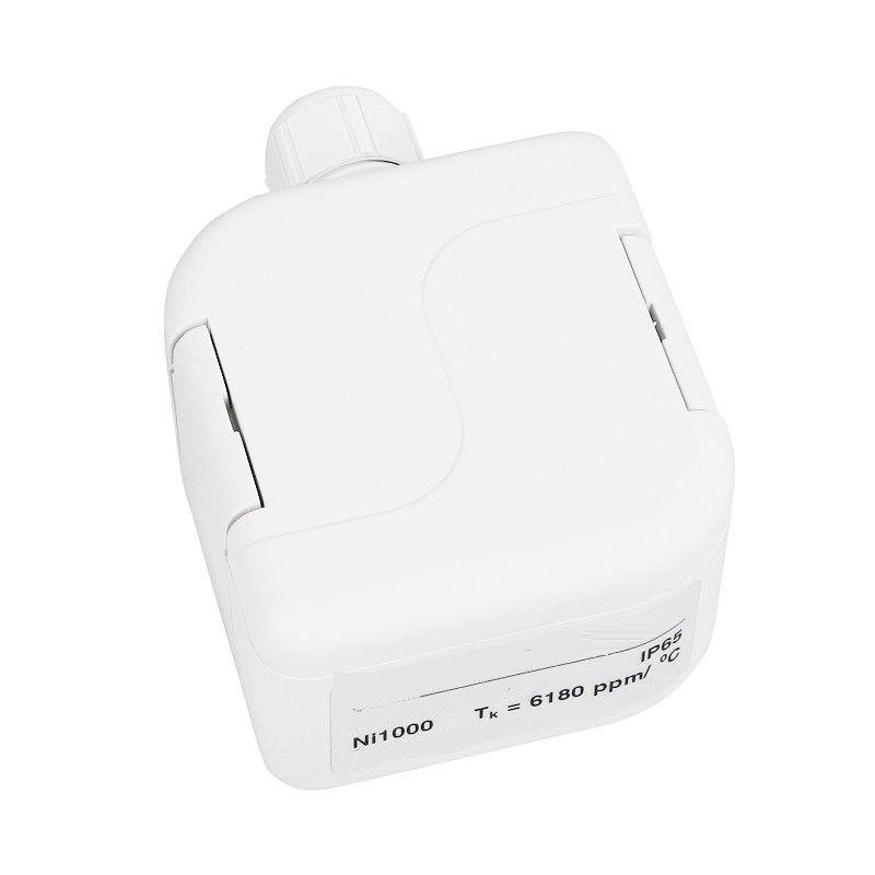
| Ingress protection | IP 65 according to EN 60529 |
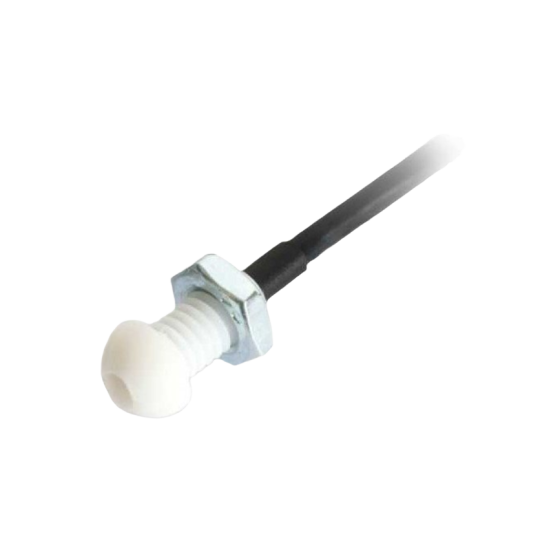
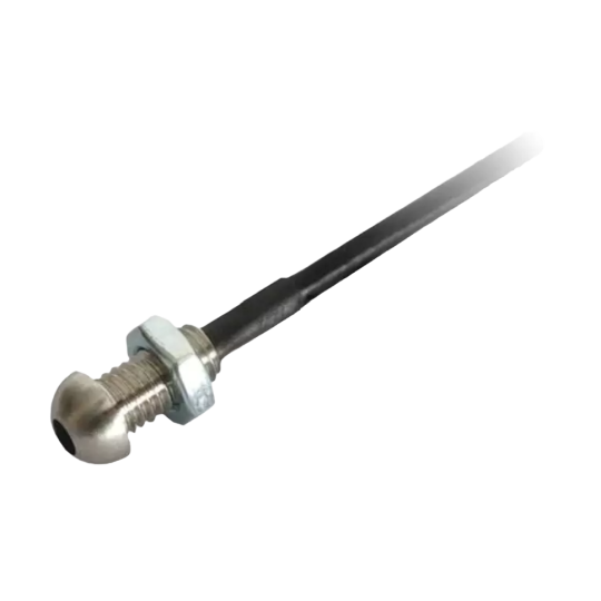
| Material of the stem |
stainless steel DIN 1.4301 - version A |
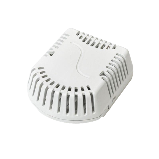
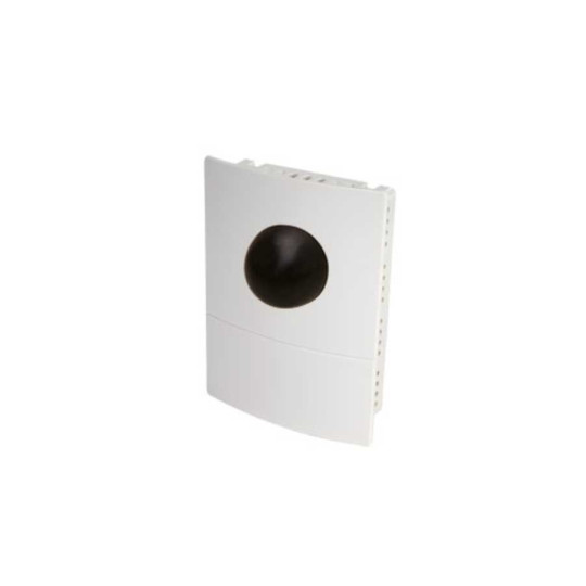
| Connection head material |
POLYAMIDE |
| Operating conditions |
ambient temperature: -50 to 100 ° C; -30 to 70 ° C with a converter |
| relative humidity: max. 100% (at room temperature 25 ° C) | |
| atmospheric pressure: 70 to 107 kPa | |
| Weight | about 0,15 kg |
SENSOR INSTALLATION AND MAINTENANCE
WELL DETECTORS:
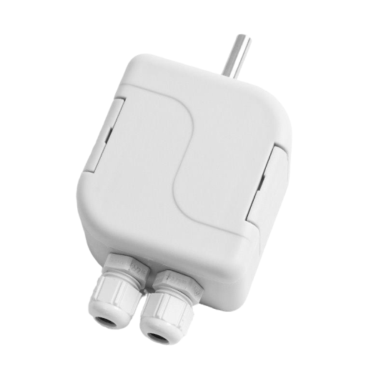
Before connecting the power cable, lift the cover of the plastic connection head using a flat screwdriver. The input cable is connected to the terminals according to the wiring diagram through the loose eyelet. The recommended wire section is 0,35 to 1,5 mm2. The diameter of the circular section cable can range from 4 to 8 mm. To ensure the IP 65 protection value, the grommet must be tight and the cover must be put on after connecting the input cable.
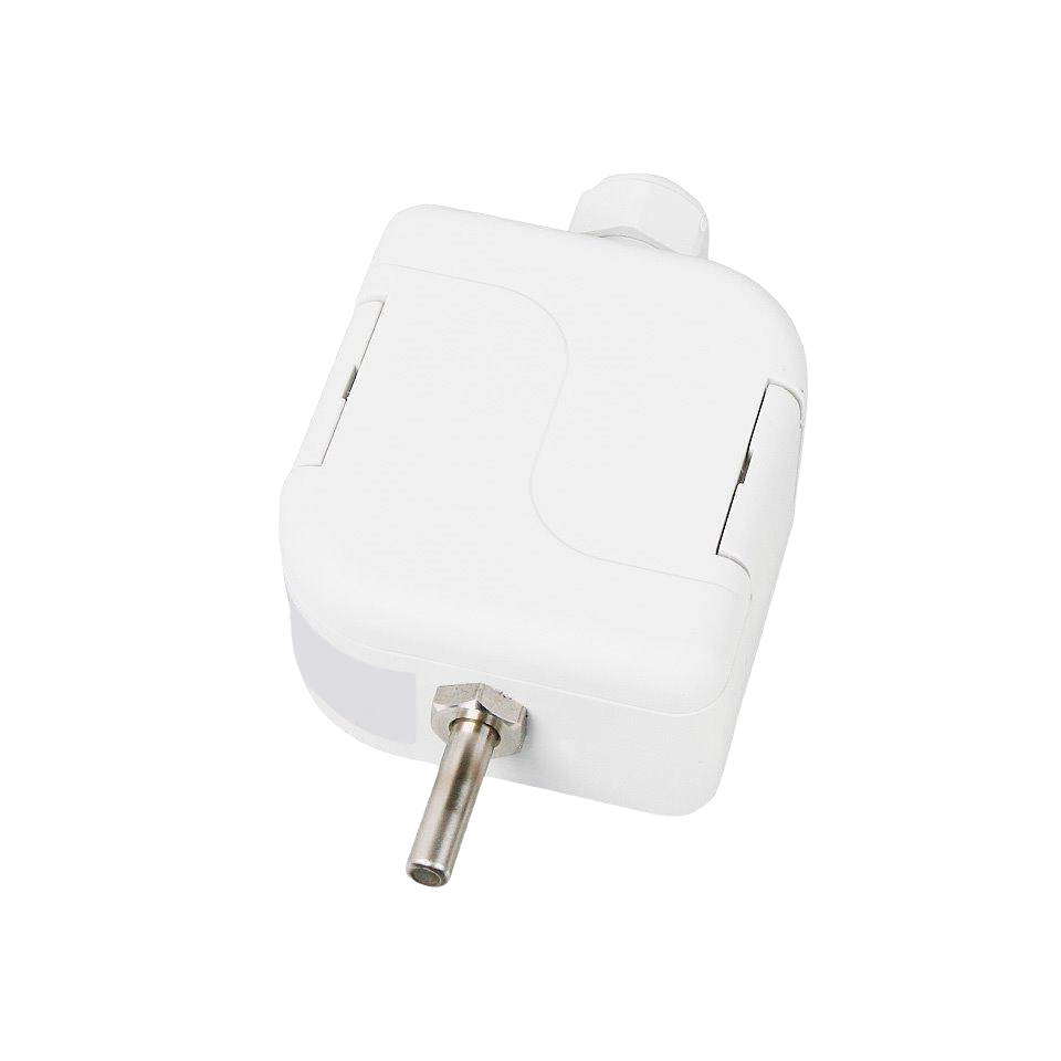
SENSORS WITH CONNECTOR:
The input cable with connector is connected to the RSFM4 connector, which is part of the sensor head. Optionally the stand-alone CONEC 43-00092 connector, or an input cable with a length of 5 m, equipped with a straight type RKT connector or a rectangular type RKWT connector can be delivered. To ensure the protection value IP 65, the connectors and the sensor cover must be tightened and checked. In the event that the input cable is laid near high voltage conductors or those supplying equipment that create an interfering electromagnetic field (for example, inductive cables).
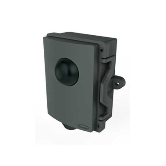
charge the equipment), a shielded cable should be used. The openings for the installation of the plastic clamp must be drilled in accordance with the sketch dimensions on which the opening diameters and the distances from their centers are illustrated. After installation and connection of the sensor to the sequential system assess the electrical equipment that the sensor is ready to use. The sensor does not require any particular maintenance. The device can be used in any working position, but the eyelet must not point upwards. The sensors are mounted using two methods: a) directly on the flat surface using two Ø 4,5 mm screws in the openings in the corners of the head. The dimension 13 mm (distance to the barrier in the head connection) must be added to the length necessary for attachment to a base; b) by means of the lateral support which must be fixed for example to a wall by means of two Ø 4,5 mm screws. To ensure watertightness, it is necessary to carefully tighten the eyelet. During the closing of the head by means of the cover the clips must be broken in the original position.
MODIFICATION AND CUSTOMIZATION FOR THE STANDARD DETECTORS MANUFACTURED, THE FOLLOWING PARAMETERS CAN BE MODIFIED:
- possibility of coating two sensitive elements.
- possibility of encapsulating non-standard temperature sensors (DALLAS, TSic, KTY, SMT, etc.).
- Accuracy class A (with the exception of Ni 10000/5000, Ni 10000/6180, T1 = Ni 2226 sensors, NTC resistance 20 kΩ).
- connection option with three or four wires.
- possibility of providing custom temperature ranges for temperature sensors with converter.