
The different types of thermistor temperature sensors
There are two types of thermistors:
- the negative temperature coefficient (NTC or CTN)
- and the positive temperature coefficient (PTC or CTP).
With an NTC probe, when the temperature increases, the resistance decreases. Conversely, when the temperature decreases, the resistance increases. This type of thermistor is the most widely used.
A PTC thermistor works a little differently. As the temperature increases, the resistance increases and as the temperature decreases, the resistance decreases. As a general rule, a thermistor achieves high accuracy in a limited temperature range of about 50 ° C around the target temperature. This range depends on the basic resistance.
thermistor symbols
The arrow next to T means that the resistance is variable depending on the temperature. The direction of the arrow or the bar is not significant.
Thermistor sensors are easy to use, inexpensive, robust, and react predictably to changes. Although they do not perform well with very low or high temperatures, they are the sensor of choice for applications that take temperature over a low measurement range. The thermistor is ideal when precise temperature control is required.
Some of the most common uses for thermistors are in digital thermometers, oil and coolant temperature measurement, household appliances such as ovens and refrigerators.
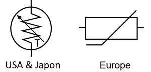 |
Figure 1: Thermistor Symbol - United States and Japan
How does the thermistor "measure" the temperature?
In reality, a thermistor does not "read" anything, the resistance of a thermistor changes with temperature. The degree of variation of the resistance depends on the type of material used in the thermistor.
Unlike other measurement probes, thermistors are nonlinear, which means that the points on a graph representing the relationship between resistance and temperature will not form a straight line. The construction of the thermistor determines the location of the line and its evolution. A typical thermistor graph looks like this:
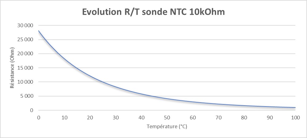 |
Figure 2: resistance as a function of temperature
What is the difference between a thermistor and other sensors?
In addition to thermistors, several other types of temperature sensors are used. The most common are resistance temperature detectors (RTDs) and integrated circuits (ICs). The measurement probe that works best for a particular purpose is based on many factors.
Temperature Range: The approximate global range of temperatures in which a probe type can be used. Within a given temperature range, some sensors perform better than others.
Cost: Relative cost when these sensors are compared to each other. For example, thermistors are inexpensive relative to RTDs, in part because the material of choice for RTDs is platinum.
Sensitivity: The approximate time required to move from one temperature value to another. This is the time, in seconds, required for a thermistor to reach 63,2% of the temperature difference between the initial reading and the last one.
What forms of thermistor are available?
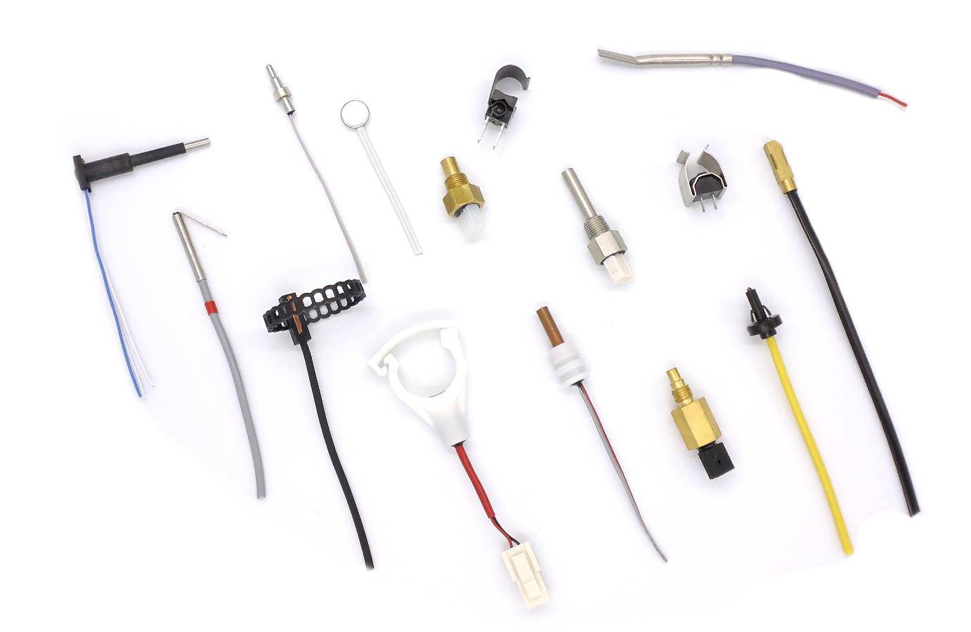 Thermistor temperature sensors come in a variety of forms—disk, chip, bead, or rod—and can be surface-mounted or integrated into a system. They can be encapsulated in epoxy resin, glass, baked phenolic resin or painted. The best shape often depends on the material being monitored, such as a solid, liquid, or gas.
A thermistor chip is normally mounted on a printed circuit board. There are many different forms of thermistors.
Choose a shape that allows maximum surface contact with the device whose temperature is being monitored. Regardless of the type of thermistor, the connection to the monitored device must be made using a high thermal conductivity paste or an epoxy adhesive. It is generally important that this paste or glue does not conduct electricity.
How does a thermistor work in a controlled system?
The thermistor is mainly used to measure the temperature of a device. In a temperature-controlled system, the thermistor is a small but important part of a larger system. A temperature controller monitors the temperature of the thermistor. It then tells a heater or cooler when to turn on or off, in order to maintain the probe temperature.
The sensor head is fixed on the cooling plate which must maintain a specific temperature to cool the device, and the wires are connected to the temperature controller. The temperature controller is also electronically connected to the Peltier device, which heats and cools the target device. The heat sink is attached to the Peltier device to facilitate heat dissipation.
The location of the thermistor probe in the system affects both the stability and measurement accuracy of the control system. For better stability, the thermistor should be placed as close as possible to the thermoelectric or resistive heater. For best accuracy, the thermistor should be located near the device requiring temperature control.
Ideally, the thermistor is built into the device, but it can also be attached using heat-conducting paste or glue. Even if a measuring device is integrated, air gaps must be eliminated with thermal paste or glue.
What are the upper and lower voltage limits at the input of the temperature sensor?
The sensor voltage limits returned to a temperature controller are specified by the manufacturer. The ideal is to select a thermistor and a combination of bias current that produce a voltage in the range allowed by the temperature controller.
Ohm's law
The voltage is related to the resistance (Ohm's law). This equation is used to determine which polarization current is needed. Ohm's law stipulates that the current passing through a conductor between two points is directly proportional to the potential difference between the two points and that, for this bias current, it is written:
U = R x I
Or:
U is the voltage, in Volts (V)
I BIAS is the current, in Amps or Amps (A)
I BIAS means that the current is fixed
R is the resistance, in Ohms (Ω)
The controller produces a bias current to convert the resistance of the thermistor to a measurable voltage. The controller will only accept a certain voltage range. For example, if a controller range is between 0 and 5 V, the voltage of the thermistor should not be less than 0,25 V so that the low-level electrical noise does not interfere with reading, and is not greater than to 5 V to be read.
Example
Suppose the use of the controller ATR121 and a 10 kΩ thermistor (B25 / 85: 3435K), such as the sensors Universal NTC waterproof 10kOhm B3435 1500mm - Guilcor , and that the temperature that the device must maintain is 20 ° C. According to the data sheet, the resistance is 10 000 Ω to 25 ° C. To determine if the thermistor can work with the controller, we must know the usable range polarization currents. Using Ohm's Law to solve I, we know the following:
V / R = I BIAS
0,25 / 10 000 = 25 μA is the lowest end of the range
5,0 / 126700 = 500 μA is the highest
Yes, this thermistor will work if the bias current of the temperature controller can be set between 25 μA and 500 μA.
When selecting a thermistor and a bias current, it is best to choose a sensor whose voltage is in the middle of the range. The return input of the controller must be energized, derived from the resistance of the thermistor.
The most accurate model used to convert the resistance of thermistors to temperature is called the Steinhart-Hart equation.
What is the Steinhart-Hart equation?
The Steinhart-Hart equation is a model that was developed in a time when computers were not ubiquitous and most mathematical calculations were done using slide rules and other mathematical tools, such as than the transcendental function tables. The equation was developed as a simple method to model thermistor temperatures easily and more precisely. The Steinhart-Hart equation is as follows:
1 / T = A + B (lnR) + C (lnR) 2 + D (lnR) 3 + E (lnR) 4 ...
Or:
T is the temperature, in Kelvin (K, Kelvin = Celsius + 273,15),
R is the resistance in T, in Ohms (Ω).
A, B, C, D and E are the Steinhart-Hart coefficients that vary with type. of the thermistor used and the temperature range detected.
ln is Natural Log or Log base Napierian 2.71828
The standard Steinhart-Hart equation used is:
1 / T = A + B (lnR) + C (lnR) 3
One of the advantages of computer programs is that equations that would have taken days or even weeks to solve are solved in moments. Type "Steinhart-Hart Equation Calculator" into any search engine and pages of links to online calculators are returned.
How is the Steinhart-Hart equation used?
This equation calculates more accurately the actual resistance of a thermistor as a function of temperature. The narrower the temperature range, the more accurate the calculation of the resistance will be. Most thermistor manufacturers provide the A, B and C coefficients for a typical temperature range.
Who are Steinhart and Hart?
John S. Steinhart and Stanley R. Hart first developed and published the Steinhart-Hart equation in an article entitled "Thermistor Calibration Curves" in 1968, while they were researchers at the Carnegie Institution in Washington. . Steinhart later became a professor of geology and geophysics, then studied marine science at the University of Wisconsin-Madison, and Stanley R. Hart became principal investigator at the Woods Hole Oceanographic Institution.
Conclusion
Thermistor sensors are temperature-dependent resistors that change resistance with changes in temperature. They are very sensitive and react to very small changes in temperature. They are best used when a specific temperature must be maintained and when monitoring temperatures within 50°C of ambient temperature.
Thermistor meters, as part of a temperature control system, are the best way to measure and control the heating and cooling of a Peltier device. Their ability to adjust per minute allows for maximum system stability. Thermistors can be integrated or surface mounted on the device requiring temperature monitoring. Depending on the type, they can measure liquids, gases or solids.
Are you looking for information about PTC and NTC sensors? Go directly to the dedicated page!
| ↓ | ↓ |
| NTC | PTC |