Conventional RTD sensing elements made of platinum, copper or nickel have a resistance relationship as a function of the repeatable temperature (R / T) and an operating temperature range. The R / T relationship is defined as the amount of sensor resistance change per degree of temperature change. The relative variation of the resistance (coefficient of thermal resistance) varies only very little over the useful range of the sensor.
 |
Platinum was proposed at the 1871 Bakerian conference: it is a noble metal with the most stable resistance-temperature relationship over the widest temperature range. Nickel elements have a limited temperature range because the R / T becomes non-linear at temperatures above 300 ° C. Copper has a very linear resistance-temperature relationship; however, copper oxidizes at moderate temperatures and can not be used at more than 150 ° C.
The significant characteristic of the metals used as resistive elements is the linear approximation of the resistance-temperature relation between 0 and 100 ° C. This coefficient of resistance temperature is denoted α and is generally given in units of Ω / (Ω · ° C ):
α = (R100-R0) / (100°C .R0)
where
R0 is the resistance of the sensor at 0 ° C,
R100 is the resistance of the sensor to 100 ° C.
Pure platinum a α = 0,003925 Ω / (Ω ° C) in the range 0 to 100 ° C is used in the construction of laboratory resistance sensors. Conversely, two recognized standards for industrial RTDs IEC 60751 and ASTM E-1137 specify α = 0,00385 Ω / (Ω · ° C). Before the widespread adoption of these standards, several different α values were used. It is still possible to find older platinum sensors having α = 0.003916 Ω / (Ω · ° C) and 0.003902 Ω / (Ω · ° C).
These different values of α for platinum are obtained by doping by carefully introducing the impurities into platinum. The impurities introduced during the doping sink into the lattice structure of platinum and cause a different R vs T curve and therefore a value α.
To characterize the R vs T relationship of any RTD over a temperature range representing the intended range of use, calibration should be performed at temperatures other than 0°C and 100°C. 'calibration. Although RTDs are considered to operate linearly, they must be proven to be accurate with respect to the temperatures at which they will actually be used. Common calibration methods are the fixed point method and the comparison method.
Is used for the highest precision calibrations by metrology laboratories. It uses the triple point, freezing point or melting point of pure substances such as water, zinc, tin and argon to generate a known and reproducible temperature. These cells allow the user to reproduce the actual conditions of the ITS-90 temperature scale. Fixed point calibrations provide extremely accurate calibrations (to ± 0,001 ° C). The ice bath is a common fixed point calibration method for industrial grade sensors. The equipment is inexpensive, easy to use, and can accommodate multiple sensors at the same time. The ice point is designated as a secondary standard because its accuracy is ± 0,005 ° C, compared to ± 0,001 ° C for the main fixed points.
The three main categories of RTD sensors are thin film and coil elements. Although these types are the most widely used in industry, other more exotic forms are used; for example, carbon resistors are used at extremely low temperatures (-173 ° C to -273 ° C). More information.
Elements of carbon resistance
Are cheap and widely used. They have reproducible results at low temperatures. They are the most reliable form at extremely low temperatures. They are not subject to significant hysteresis or strain gage effect.
Elements without constraint
Use a wire spool that is minimally supported in a sealed housing filled with an inert gas. These sensors operate up to 961,78 ° C and are used in the SPRTs that define the ITS-90. They consist of platinum wire lightly wound on a support structure, so that the element is free to expand and contract with temperature. They are very sensitive to shocks and vibrations because platinum loops can swing and warp.
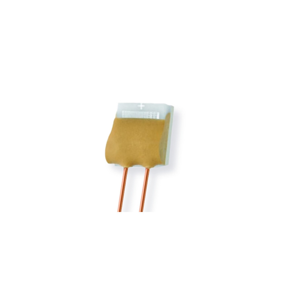
Thin film elements
Have a sensitive element that is formed by depositing a very thin layer of resistive material, normally platinum, on a ceramic substrate (veneer). This layer usually has a thickness of 10 to 100 ångströms (1 to 10 nanometers). This film is then coated with an epoxy or glass that helps protect the deposited film and also serves as a strain relief for the outer conductors. The disadvantages of this type are that they are not as stable as their coiled counterparts. They can also be used only over a limited temperature range because of the different expansion rates of the substrate and the resistive deposit giving a "strain gage" effect visible on the resistive temperature coefficient. These elements operate at temperatures up to 300 ° C without further packaging, but can operate up to 600 ° C when properly encapsulated in glass or ceramic. Special RTD elements at high temperature can be used up to 900 ° C with good encapsulation.
Wound elements
may have greater accuracy, especially for wide temperature ranges The diameter of the coil offers a compromise between mechanical stability and yarn expansion to minimize stress and consequent drift. The sensing wire is wrapped around a mandrel or an insulative core. The core of the coil may be round or flat, but must be an electrical insulator. The coefficient of thermal expansion of the winding core material is adapted to the sensing wire to minimize any mechanical stress. This stress on the wire of the element will lead to a thermal measurement error. The sense wire is connected to a larger wire, usually referred to as the wire or element of the element. This wire is selected to be compatible with the sense wire, so that the combination does not generate an electromotive force that would distort the thermal measurement.
Coiled elements
Have largely replaced the wound elements in the industry. This design has a coil of wire that can expand freely over temperature, held in place by mechanical support, allowing the coil to retain its shape. This "unrestrained" design allows the sensing wire to expand and contract without the influence of other materials; in this respect, it is similar to the SPRT, the main standard on which ITS-90 is based, while offering the durability necessary for industrial use. The base of the sensing element is a small coil of platinum sensing wire. This coil looks like a filament in an incandescent bulb. The housing or mandrel is a hard-cooked ceramic oxide tube with equidistant bores that extend transversely to the axes. The spool is inserted into the bores of the mandrel and then packaged with a very finely ground ceramic powder. This allows the sensor wire to move while remaining in thermal contact with the process. These elements operate at temperatures up to 850 ° C.
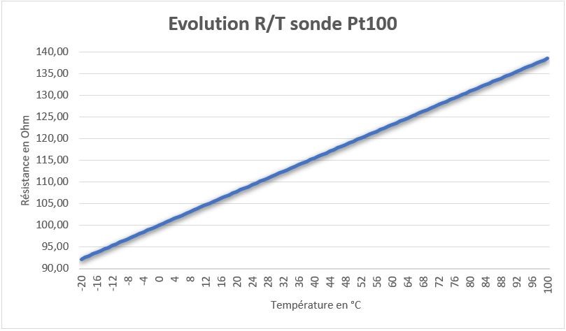
The current international standard that specifies the tolerance and relationship between resistance and electrical resistance of platinum resistance thermometers is IEC 60751: 2008; ASTM E1137 is also used in the United States. The most commonly used devices in the industry have a nominal resistance of 100 ohms at 0 ° C and are called Pt100 sensors ("Pt" is the platinum symbol, "100" is the resistance in ohms at 0 ° C). It is also possible to obtain Pt1000 sensors, where 1000 corresponds to the ohms resistance at 0 ° C. The sensitivity of a standard 100 Ω sensor is 0,385 Ω / ° C. RTDs with a sensitivity of 0,375 and 0,392 Ω / ° C, as well as many others, are also available.
Is commonly used with secondary SPRTs and industrial RTDs. The thermometers being calibrated are compared with the calibrated thermometers by means of a bath whose temperature is uniformly stable. Unlike fixed point calibrations, comparisons can be made at any temperature between -100 ° C and 500 ° C. This method could be more cost effective because multiple sensors can be calibrated simultaneously with automated equipment. These electrically heated and well-stirred baths use silicone oils and molten salts as the medium for the different calibration temperatures.
Resistance thermometers are built in a number of forms and in some cases offer greater stability, accuracy and repeatability than thermocouples. While thermocouples use the Seebeck effect to generate a voltage, resistance thermometers use an electrical resistor and require a power source to operate. Resistance ideally varies almost linearly with temperature according to the Callendar - Van Dusen equation.
Platinum sensing wire must remain free of contamination to remain stable. A platinum wire or film is supported on a jig so as to obtain minimal differential expansion or other deformations of its jig, while reasonably resisting vibration. Iron or copper RTD assemblies are also used in some applications. The commercial grades of platinum have a temperature resistance coefficient of 0,00385 / ° C (0,385% / ° C) (European fundamental range). The sensor is typically designed to have a resistance of 100 Ω to 0 ° C. This is defined in BS EN 60751: 1996 (taken from IEC 60751: 1995). The fundamental American interval is 0,00392 / ° C, based on the use of platinum quality purer than the European standard. The American standard comes from the SAMA (Scientific Apparatus Manufacturers Association), which is no longer in this area of standards.
The resistance of the conducting wire can also be a factor; by adopting three- and four-wire connections, instead of two wires, the resistance of the connections can be subtracted. The three-wire connection is sufficient in most cases and is an almost universal industrial practice. Four-wire connections are used for the most accurate applications.
The advantages of platinum resistance thermometers:
- High accuracy
- Low drift
- Wide operating range
- Suitable for precision applications
limitations:
RTDs in industrial applications are rarely used above 660 ° C. At temperatures above 660 ° C, it is increasingly difficult to prevent platinum from being contaminated by impurities from the metallic sheath. thermometer. This is why standard laboratory thermometers replace the metallic sheath with a glass construction. At very low temperatures, for example below -270 ° C (3 K), because of the rarity of the phonons, the resistance of an RTD is mainly determined by the impurities and the limiting diffusion, and is therefore fundamentally independent of the temperature. As a result, the sensitivity of the RTD is essentially zero and therefore useless.
Compared with thermistors, platinum RTDs are less sensitive to small temperature changes and have a slower response time. However, the thermistors have a temperature range and a smaller stability.
RTD vs. thermocouples
The two most common methods of measuring temperature for industrial applications are resistance temperature detectors (RTDs) and thermocouples. The choice between them is usually determined by four factors.
Temperature
If the process temperature is between -200 and 600 ° C (we can offer Platinum sensors up to 1000 ° C for specific needs), the RTD is the most suitable option. Thermocouples have a range of -270 to 2 ° C.
Response time
If the process requires a very fast response to temperature changes, a thermocouple is the best choice. The response time is measured by immersing the sensor in water moving at 1 m / s. The time required to reach 63,2% of the setpoint corresponds to the response time.
Select
A standard RTD sheath has a diameter of 1,5mm to + of 6mm; the cladding diameters of the thermocouples may be less than 1,5 mm.
Precision and stability requirements
If a tolerance of 2 ° C is acceptable and the highest level of repeatability is not required, a thermocouple will be used. RTDs are capable of greater accuracy and can maintain stability for many years, while thermocouples can drift from the first hours of use.
These elements almost always require isolated conductors. Insulations made of PVC, silicone rubber or PTFE are used at temperatures below about 250 ° C. Above, glass fiber or ceramic is used. The measuring point, and usually most conductors, require a protective housing or sleeve, often made of a metal alloy that is chemically inert to the process being monitored. The selection and design of protective sheaths may require more care than the sensor itself, as they must withstand chemical or physical attack and provide convenient attachment points.
Standard Platinum Resistance Thermometers (SPRTs) are the highest accuracy of any PRT tool. This precision is achieved at the expense of durability and cost. SPRT elements are wound from reference platinum wire. The internal lead wires are usually platinum, while the internal brackets are quartz or fused silica. The sheaths are generally made of quartz. A larger diameter platinum wire is used, which increases the cost and reduces the resistance of the sensor (typically 25,5 Ω). SPRTs have a wide temperature range (-200 ° C to 1000 ° C) and an accuracy of approximately ± 0,001 ° C over the temperature range. SPRTs are only suitable for laboratory use.
Standard secondary platinum resistance thermometers (SPRTs) are another classification of laboratory PRTs. They are built like SPRT, but the materials are more profitable. SPRTs commonly use platinum wire, metallic sheaths and ceramic insulators of superior quality, of lower purity. Internal lead wires are generally a nickel-based alloy. Secondary SPRTs are more limited in the temperature range (-200 ° C to 500 ° C) and have an approximate accuracy of ± 0,03 ° C for the temperature range.
Industrial PRTs are designed to withstand industrial environments. They can be almost as durable as a thermocouple. Depending on the application, industrial PRTs may use thin film or wound elements. Internal lead wires can range from PTFE insulated nickel-plated copper to silver wire, depending on the size of the sensor and the application. The material of the sheath is generally made of stainless steel. Other materials are used for specialized applications.
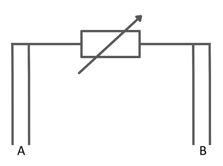
Two-wire configuration
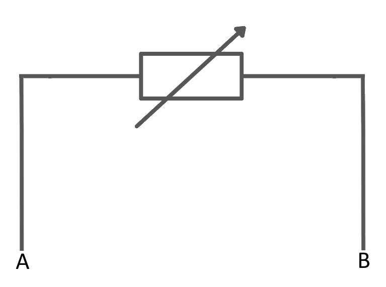 The simplest resistance thermometer configuration uses two wires. It is only used when high accuracy is not required, as the resistance of the connecting wires is added to that of the sensor, which leads to measurement errors. This configuration allows you to use 100 cable meters. This also applies to the balanced bridge and the fixed bridge system.
For a balanced bridge, the usual setting is R2 = R1 and R3 in the middle of the RTD range. So, for example, if we measure between 0 and 100 ° C, the RTD will be between 100 Ω and 138,5 Ω. We would choose R1 = 120 Ω. In this way, we obtain a small measured voltage in the bridge.
Three-wire configuration
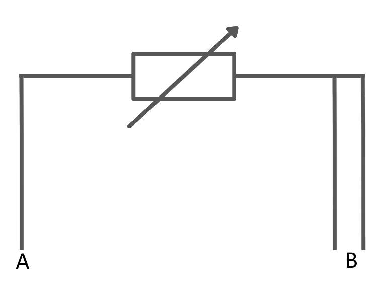 In order to minimize the effects of conductor resistances, a three-wire configuration can be used. The suggested setting for the configuration shown is with R1 = R2 and R3 in the middle of the RTD range. Looking at the Wheatstone bridge circuit shown, the voltage drop on the lower left side is V_rtd + V_lead and the lower right size on V_R3 + V_lead, so the bridge voltage (V_b) is the difference, V_rtd - V_R3. The voltage drop due to the resistance of the cable has been canceled. This still applies if R1 = R2 and R1, R2 >> RTD, R3. R1 and R2 can be used to limit the current through the RTD. For example, for a PT100 limited to 1 mA and 5 V, an approximate limiting resistance of R1 = R2 = 5 / 0,001 = 5 Ohms.
Four-wire configuration
 The four wire resistance configuration increases the measurement accuracy of the resistor. Four-point detection eliminates the voltage drop in the test leads as a contribution to the error. To further increase accuracy, all residual thermoelectric voltages generated by different types of wires or screw connections are eliminated by reversing the 1 mA current direction and DVM (digital voltmeter) taps. Thermoelectric voltages will only be produced in one direction. By averaging the inverted measurements, the thermoelectric error voltages are suppressed.