ALL ABOUT
Pt1000 resistance sensors

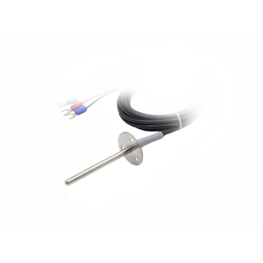
A PT1000 element consists of a coil of wire or a deposited film of pure metal. The resistance of the element increases with temperature in a known and repeatable way. Pt1000 temperature probes have excellent accuracy over a wide temperature range.
- Temperature range: -200 to 700 degrees celsius
- Sensitivity: The voltage drop across a resistance temperature detector (RTD) provides a much greater output than a thermocouple.
- Linearity: Platinum and copper resistance thermometers produce a more linear response than thermocouples or thermistors. RTD nonlinearities can be corrected with the proper design of resistive bridge networks.
The most commonly used material is platinum with a resistance of 1000 ohms at 0ºC and a temperature coefficient (Alpha) of 0,0385 ohms / ºC.
Other elemental materials also used are copper, nickel and nickel-iron are also used for the design of PT1000 measuring devices. However, platinum elements predominate because of their wider range, and because platinum is the most repeatable and stable of all metals.
| CLASS B | ± 0,30ºC |
| CLASS A | ± 0.15ºC |
| 1/3 B (1/3 DIN) | ± 0,10ºC |
| 1/10 B (1/10 DIN) | ± 0.03ºC |
Different types of connection. standard color code; A is white, B is red.
 |  |  |  |
| 2 Wires: Basic connection where the conductor is short. No compensation wire. | 3 Wires: The most common with 3 connection wires, the instrument measures the resistance of wire B and deduces it from its measurement. | 4 Wires: The 4-wire connection offers high measurement accuracy. The instrument measures the resistance of the four conductor wires and deduces it from its measurement. | Double Pt1000: 3-wire double RTD connection with two different sensitive elements. |
No maintenance is required for RTD temperature sensors, however, scheduled calibration checks at ice point (0ºC) are recommended.

Before determining the resistance of the measuring system, an insulated container with a depth of at least 300 mm and an internal diameter of 100 mm must be prepared.
PROCEDURE. The procedure should be as follows:
a) Fill the insulated container with finely divided ice made from distilled water.
Note: If the chilled water of distilled water is not available, the transparent part of a block of commercial ice will suffice, provided that all surfaces are first washed with distilled water.
b) Mix ice with water distilled previously cooled using the stirrer, then drain the excess water. The ice should be glassy but there should be no free water left.
c) Connect the thermometer to a measuring device resistance and adjust so that the electrical power dissipated in the element does not exceed 1 m W.
d) Immerse the thermal probe in the ice so that the element is at a depth of at least less 150 mm. Make sure that the lower part in the probe is at least 30 mm from the bottom of the container. Note: Thermometers with stem lengths less than 150 mm should be submerged to their maximum possible depth.
e) When the element reaches equilibrium with the ice, it is possible to measure the temperature. Measurements made with direct current should be made with current in both forward and reverse directions. Note: The time it takes for the element to reach equilibrium is normally about 3 minutes.
f) Decrease the immersion depth of the element by 50 mm or 20% of the length of the rod, the smaller of the two.
g) Repeat step (e). If the reading change is more than one-third of the appropriate tolerance, the whole procedure should be repeated with fresh ice.
Accuracy: RTD Pt1000 sensors; at 0 ºC = Class B +/- 0,3 ºC, Class A +/- 0,15 ºC, 1/10 DIN = +/- 0,03 ºC

The current through the PT100 resistance sensor will cause heating: for example, a sensing current of 1 mA through a 1000 ohm resistor will generate 1 mW heat. If the sensor element fails to dissipate this heat, the temperature value will be artificially bred. This effect can be reduced either by using a large sensor element or by ensuring that it is in thermal contact with its surroundings.
The use of a detection current of 1 mA will give a signal of only 1V. Because the change in resistance for one degree Celsius is very small, even a small error in measuring the voltage across the sensor will produce a large error when monitoring temperatures. For example, a voltage measurement error of 1mV will give an error of 0,4 ° C in the temperature reading. Likewise, a 10 μA error in the sense current will result in a temperature difference of 0,4°C.
Due to the low signal levels, it is important to keep cables away from electrical cables, motors, equipment and other devices that may emit electrical noise. Using a shielded cable with the screen grounded at one end can help reduce interference. When using long cables, it is necessary to check that the measuring equipment is able to withstand the resistance of the cables.
I CAN'T FIND MY PROBE , HOW CAN YOU HELP ME?
We will always be able to offer you the reliable, precise and robust probe you are looking for.
On our website we present a wide variety of temperature probes. Know that you can also customize your product on all specifications or make a request starting from a technical drawing in order to create your probe. To this end, do not hesitate to contact us for a tailor-made offer. We then take care of delivering your temperature probe to you as soon as possible.
