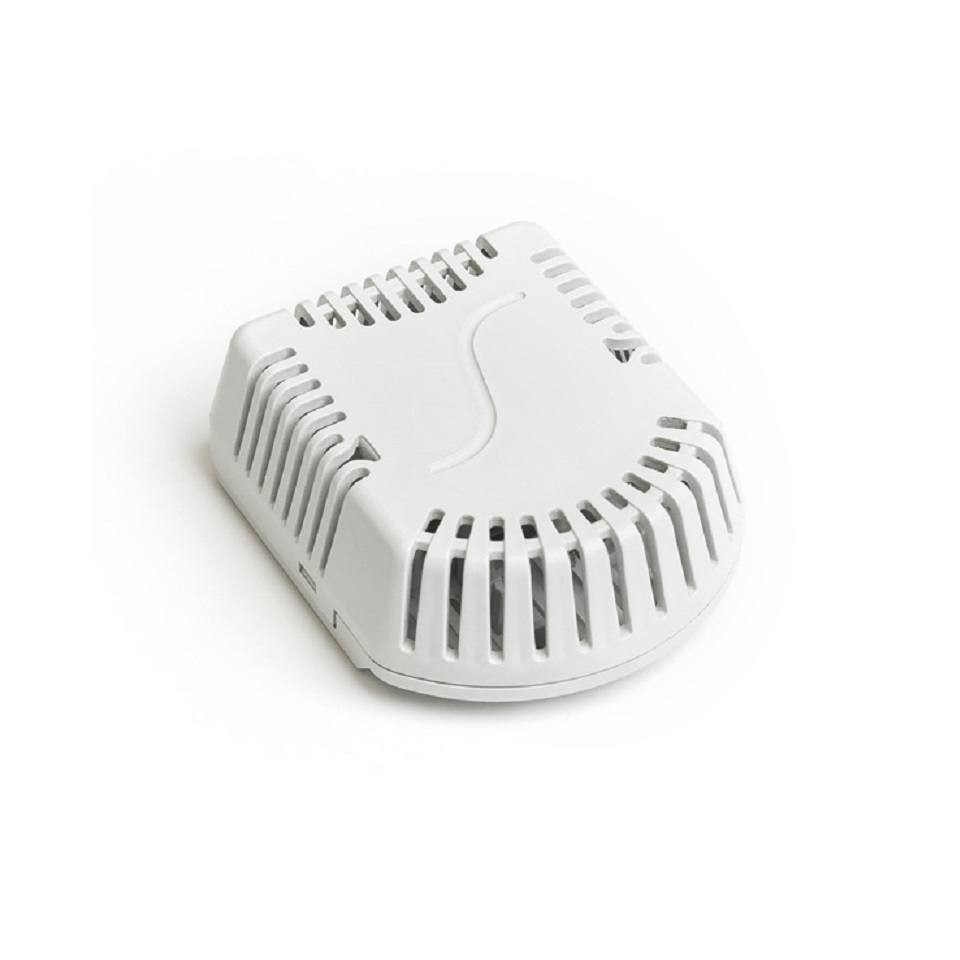


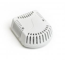
Temperature and humidity probe - CAN
Reference GSTH104R
Product features Temperature and humidity probe - CAN
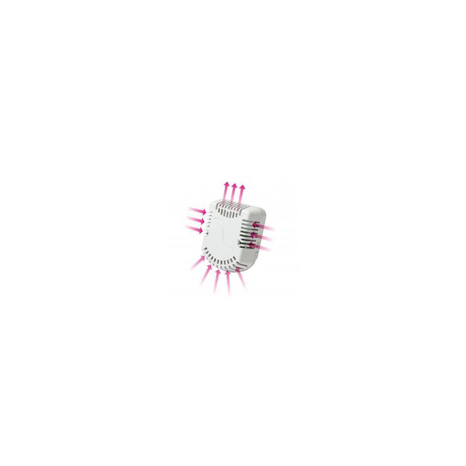
Temperature and relative humidity sensor - STH 104 is designed to operate in a chemically non-aggressive environment. The method of use must be chosen according to the temperature and the chemical resistance of the head. STH 104 temperature and relative humidity sensor. The operating conditions to ensure correct operation are as follows:
- ambient temperature: -40 to 80 ° C
- relative humidity: 0 to 95% (non-condensing)
- atmospheric pressure: 87 to 106 kPa
| Sensor type | STH-104 |
| Temperature measurement range | -40 to 80 ° C |
| Temperature measurement accuracy | ± 0,5 ° C in the range of 0 to 65 ° C ± 0,7 ° C in the range of 65 to 80 ° C ± 1,1 ° C in the range of -40 to 0 ° C |
| Relative humidity measurement | 0 to 95% |
| Relative humidity measurement accuracy | ± 3% in the range of 10 to 90% ± 4,5% in the range of 0 to 10% and 90 to 95% |
| Output signal | CAN / CANopen-CiA DS 301 |
| Galvanic isolation | No, can be provided on request |
| Supply voltage | 15 to 30 V DC |
| Nominal supply voltage U n | 24 V DC |
| The consumption | max: 500mW typical: 300 mW |
| Degree of protection | IP 30 according to EN 60529 |
| Head dimensions | 71,9 x 59 x 27 mm |
| Head material | lexan |
| The weight | min 35g |
| Recommended conductor cross-section | 0,14 to 1 mm 2 |
Note: The manufacturer reserves the right to modify the design and technical characteristics of the products.
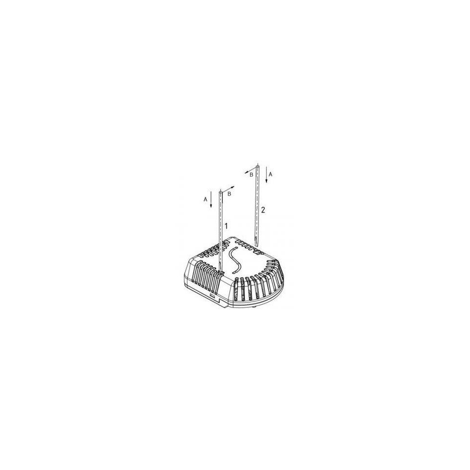
SENSOR INSTALLATION AND MAINTENANCE
The sensors are designed to be mounted on a wall or other vertical surface. For fixing, it is necessary to prepare the required holes for mounting screws using a template (supplied with the sensor).
Before connecting the power cable, it is necessary to separate the perforated cover from the plastic base. Remove the cover and insert the cable through the 9 mm hole, apply the base to the surface and screw with two screws or bolts. The length of the bolts or fixing screws for fixing should be chosen according to the thickness of the plastic base. Connect the power cable to the terminals in accordance with the “Wiring” section. Diagram: place the perforated cover on the fixed base and lock it by clicking on it. After installation and connection to the electrical measuring device, the sensor is ready for use. The sensor does not require any particular maintenance.